Day 1 · Acquisition, preprocessing, and the GLM

Day 1Session 1.1Kiehl1:00 hLecture

Virtual tours of MRI and acquisition of data, stimulus presentation, behavioral monitoring

A walk through the scanner suite from the participant's point of view: screening and clothing, the magnet room, positioning and comfort, and the control room where stimulus delivery, response logging, and eye tracking are synchronized to the scanner. Ends with a practical protocol for prescribing EPI slices consistently across participants. Good data start with a comfortable, still participant and a timing chain that trusts the scanner clock.

Take-aways

  • Participant comfort and immobility are set up before the scan begins: clothing, padding, leg position, eye position.
  • Log every stimulus and response against the scanner's own TR pulses so timing can always be reconstructed.
  • Prescribe slices along the OFC plane, top slice just above gray matter, and do it identically for every participant.

Key terms

  • MRI safety screening
  • head restraint
  • response device
  • CIRC
  • TTL scanner pulse
  • eye tracking
  • slice prescription
  • AC-PC line
  • orbitofrontal cortex (OFC) plane
  • susceptibility artifact
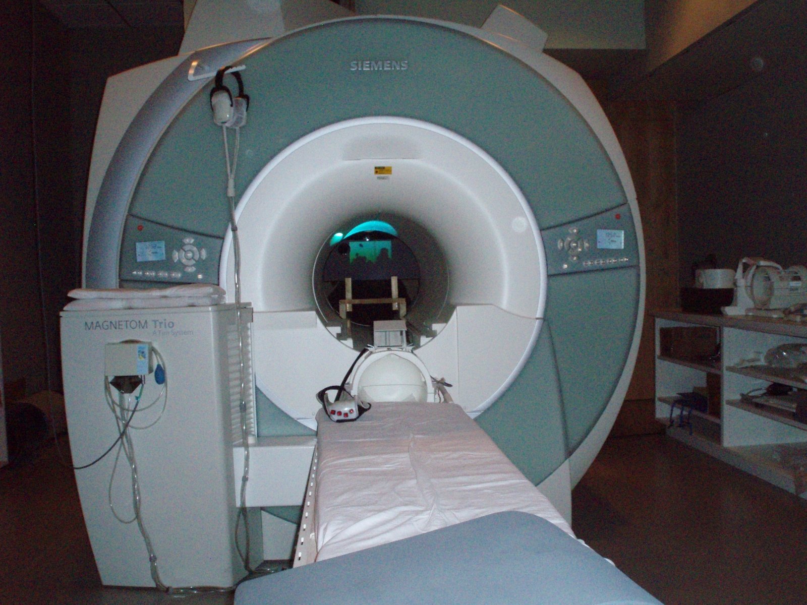
MRI scanner suite with patient table
MRI scanner suite with patient table. Lecture 1.1 slides (Kiehl)

Outline

What the session covers

01Participant screening and preparation

  • Standard screening covers metal implants, bullets, braces, hair clips, pregnancy, and tattoos (rules are IRB-specific).
  • Have participants use the bathroom first; change into scrubs, sweats, or a jumpsuit; no shoes, no underwire or sports bras, no jeans.
  • Contact lenses only if the participant normally wears them; otherwise MRI-compatible glasses.
  • Keep the clothing conversation professional and consistent across participants.

02The magnet room

  • Bed, pillow system, and head restraint (the Pearltec MULTIPAD is the presenter's favorite).
  • Visual presentation via front projection, rear projection, or goggles on a high-resolution screen.
  • Sound via pneumatic or electrostatic headphones with about 20 dB of attenuation.
  • Keep all electronics outside the magnet room and keep duplicates of every piece of hardware as backup.
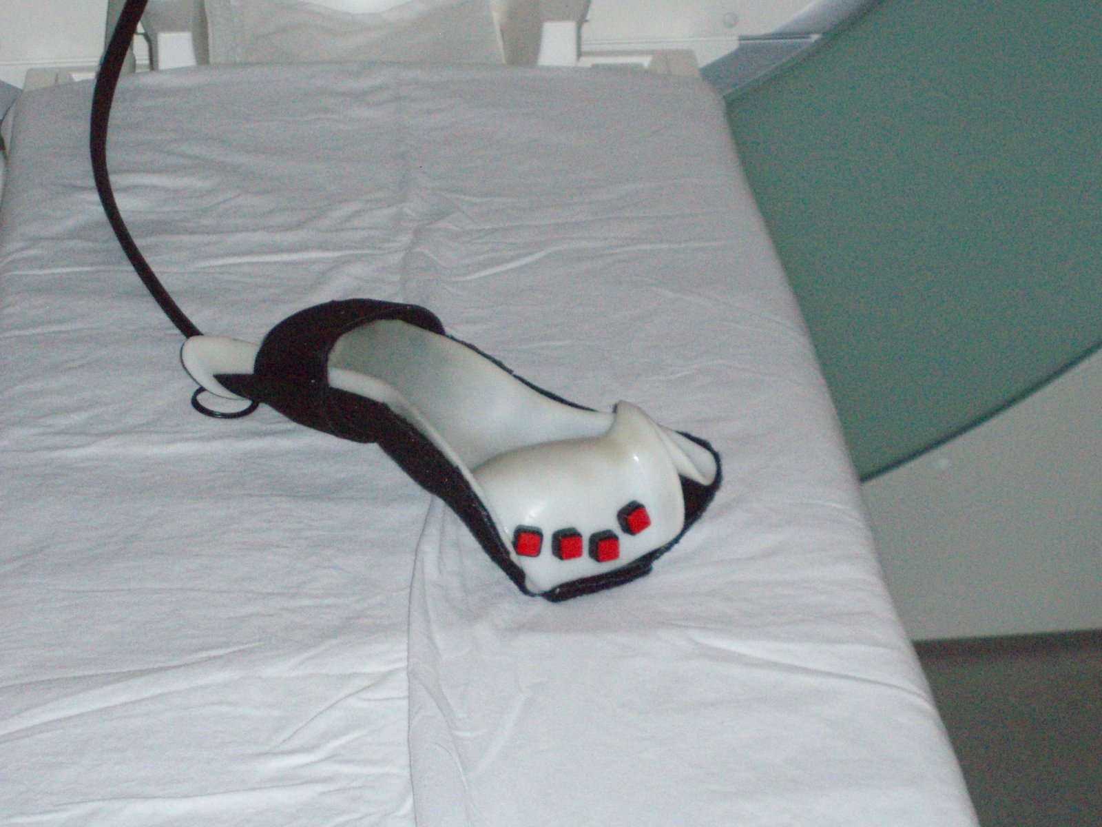
  • Response devices (e.g., NAtA Technologies button boxes) are MRI-compatible and tested before each session.
MRI-compatible response glove on the scanner bed
MRI-compatible response glove on the scanner bed. Lecture 1.1 slides (Kiehl)
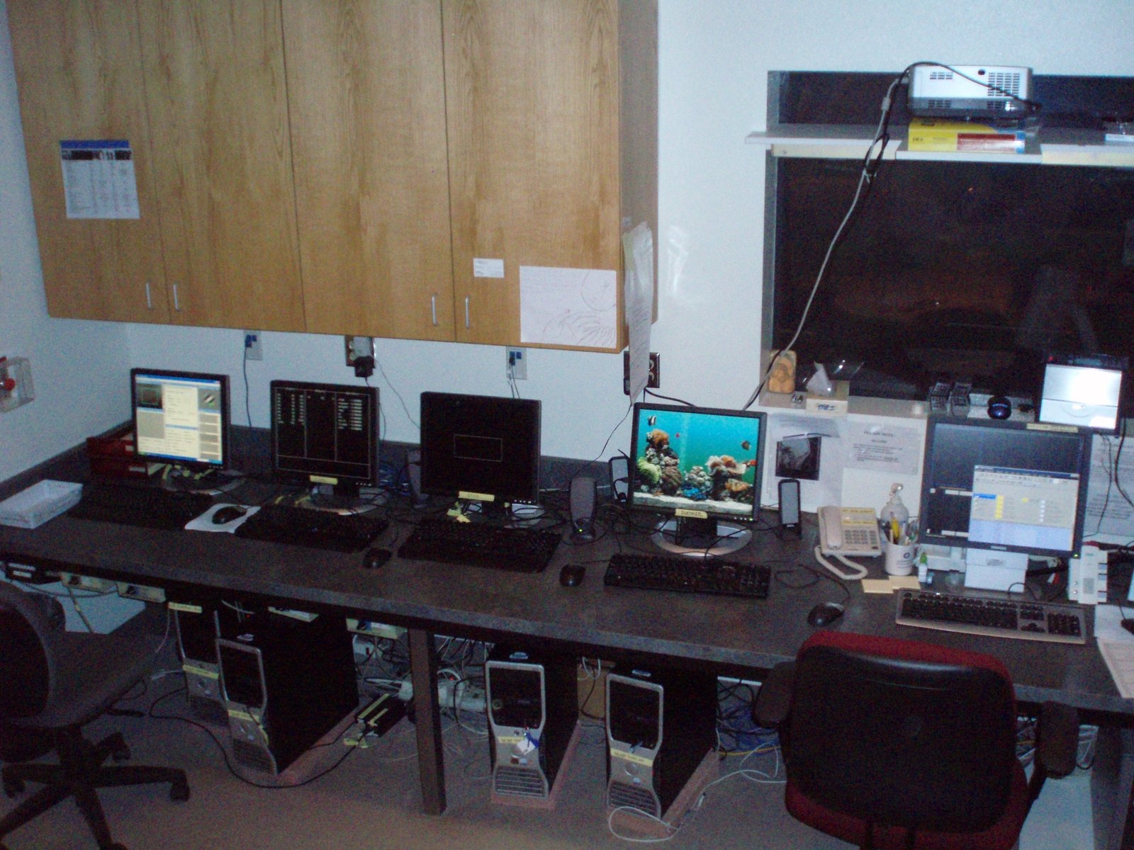
Scanner control room with operator consoles
Scanner control room with operator consoles. Lecture 1.1 slides (Kiehl)

03Positioning and comfort

  • Elevate the legs and keep them uncrossed; side pillows keep arms off the cold bore and reduce current loops.
  • Eye position is the most important trick for comfortable, still participants; a blanket and squeeze ball help.
  • Eye tracking is always worthwhile for monitoring alertness and compliance.
  • A soother display helps reduce claustrophobia.

04Control room: stimulus presentation and behavioral monitoring

  • Four screens: soother, stimulus presentation, CIRC (behavioral recording), eye tracking, plus the MRI console.
  • Use dedicated computers, not laptops; keep separate development machines elsewhere in the building.
  • CIRC shows three columns: inputs (event and response codes), output codes, and summary variables (RT, d-prime, beta, hits, misses, false alarms).
  • The scanner dictates time: its pulse starts stimulus presentation, and each TR a TTL pulse is converted to an 8-bit byte and logged in CIRC.
  • This lets every stimulus be re-synchronized to scanner time even if the presentation program drifts, which matters for both fast and slow fMRI.

05Prescribing EPI slices consistently (cheat sheet)

  • Slice orientation and angle change the pattern of susceptibility artifacts, so prescribe slices the same way for every participant.
  • Use oblique axial slices rather than true axial; this reduces truncation of the brain in large heads.
  • Simple rule: align the slice plane with the orbitofrontal cortex, about 20 degrees up from the AC-PC line.
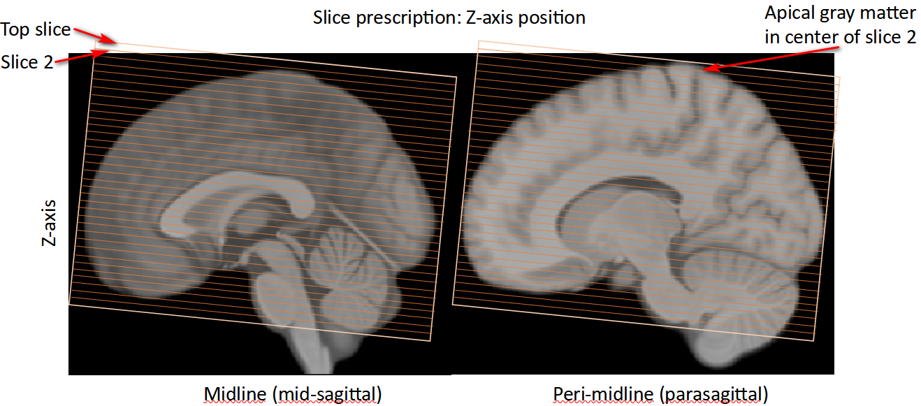
  • Place the top slice one slice above the gray matter so sensorimotor cortex sits in the second slice from the top.
  • For very large heads this sacrifices caudal brainstem and cerebellum, which have poor signal anyway, in favor of sensorimotor coverage.
  • Structural and diffusion scans typically use a different prescription.
Five dynamic connectivity states rendered on cortical surfaces — Rashid et al. (2014), Frontiers in Human Neuroscience

Hands-on

Step by step

The walk-through below is distilled from the course cheat sheets. Data paths refer to the course Dropbox folder (e.g. data/auditory_oddball).

Sample fMRI slice protocol — full cheat sheet

It’s important to be consistent in how slices are prescribed across participants, because different orientations and angles produce different patterns of susceptibility artifacts. This document outlines a method of prescribing slices for Echo Planar Imaging BOLD fMRI that aims to help ensure consistency of imaging data across scans and sites. It prioritizes coverage of the dorsal part of the cerebral cortex (i.e., sensorimotor cortex) and signal quality in the orbitofrontal cortex.

Note: This is intended for functional scans. Structural and diffusion scans will often have a different slice prescriptions.

Slice orientation

If slices are not rotated, then images are “true axial” and oriented to the scanner bore. Rotation of this slice plane (aka “angulation” or “oblique” scanning) is a standard practice and results in “axial” scans. Rotation will allow for a level of consistency across subjects and is more likely to avoid truncation of the brain, particularly for subjects with large crania [1].

Axial scans can follow a variety of protocols for establishing the slice plane, the most common of which for MRI the AC-PC line [2]. (See “AC-PC Location” below.) This requires locating the anterior and posterior commissures, which are small structures, and this can be challenging using localizer images.

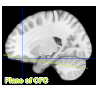
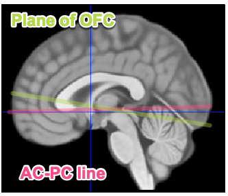
The proposed slice orientation protocol uses a simpler method: slice prescription should follow the plane of the orbitofrontal cortex (OFC; Figure 2). This is tilted approximately 20 degrees up from the AC-PC line, so that the anterior portion of the slices are slightly above the AC-PC line and posterior portion below the AC-PC line (Figure 3).

Figure 2: Slice plane oriented to match orbitofrontal cortex (OFC) in parasagittal view.
Figure 3: Plane of OFC (slice plane) tilted up relative to AC-PC line in sagittal midline view.

Field of view

The apical (top) portion of the cortex (sensorimotor cortex) should lie in the center of the 2nd-slice from the top (Figure 4). Put another way: Prescribe the slices so that the top slice is one slice above the gray matter. This avoids positioning gray matter in the top slice, which is subject to artifacts related to head movement, while retaining as much coverage of the whole brain as possible.

In rare cases when the head is particularly large, this positioning will sacrifice coverage of the caudal brainstem and cerebellum, which has poor signal quality and coverage across studies, preserving coverage of sensorimotor cortex.

Figure 4:

AC-PC Location

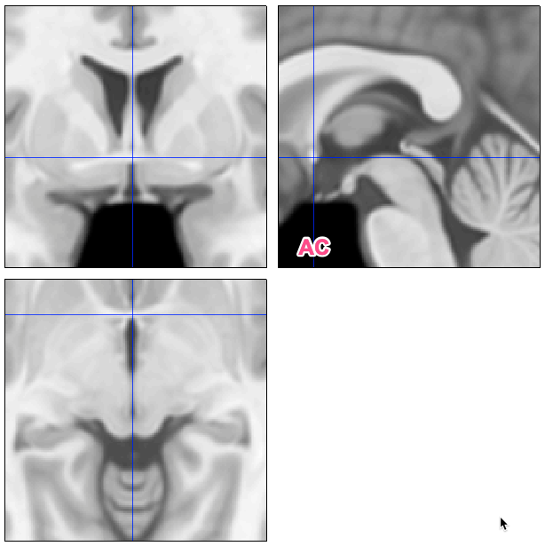
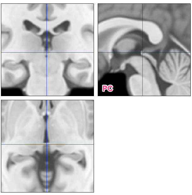
The anterior commissure (AC) and posterior commissure (PC) are white matter tracts connecting the hemispheres (Figure 1).

Figure 1: AC and PC locations (crosshairs in three orthogonal views) on template brain.

References

[1] Mennes et al. (2014). Optimizing full-brain coverage in human brain MRI through population distributions of brain size. Neuroimage 98: 513-20. doi: 10.1016/j.neuroimage.2014.04.030

[2] Otake et al. (2018). A guide to identification and selection of axial planes in magnetic resonance imaging of the brain. Neuroradiol J 31(4): 336–344. doi: 10.1177/1971400918769911

From the instructors' research

Related figures

Examples of these concepts in published work by the course instructors.

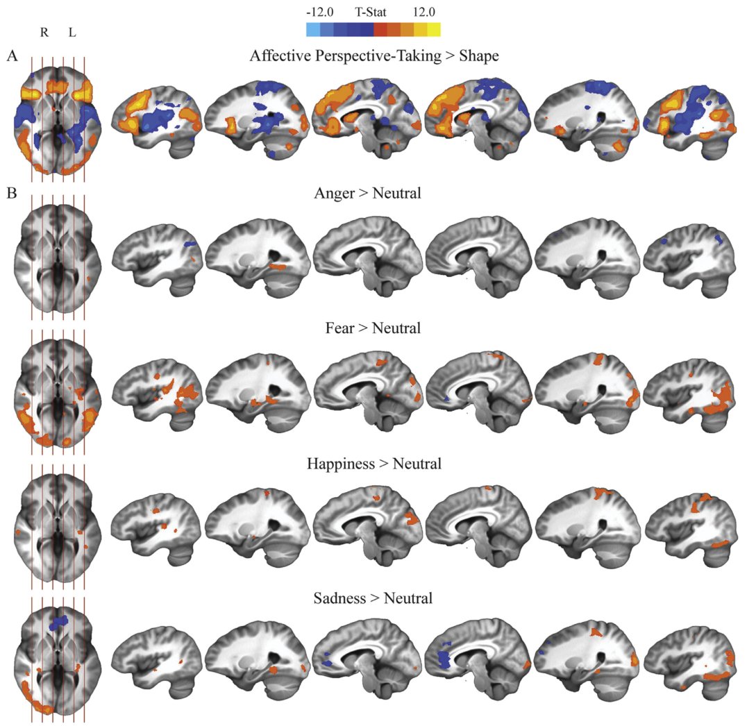
Affective perspective-taking activation maps by emotion
Affective perspective-taking activation maps by emotion. Deming et al. (2020), NeuroImage
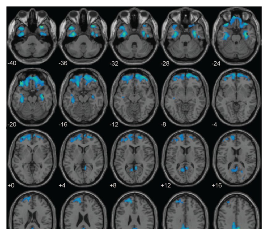
Paralimbic gray matter reductions associated with psychopathy
Paralimbic gray matter reductions associated with psychopathy. Ermer et al. (2012), Journal of Abnormal Psychology